Friday, October 4, 2019

PROPERTIES TO PARAMETERS (P2P) and some VBA!

Did not quite make the weekly update as discussed in the last posting, but two weeks is still better than three years.

In the past we had pushed properties into a parameter so the parameter could be used in a sketch to create a feature, but due my faulty memory, I could not recall how it was accomplished previously. 

So some research was undertaken and some iLogic was created.

This post at cadline community was used to develop the iLogic code.

Sub Main()

 Dim oDoc As Inventor.PartDocument 

 If ThisDoc.Document.DocumentType <> kPartDocumentObject Then
  Exit Sub
 Else
  oDoc = ThisDoc.Document
 End If

 Dim customPropSet As PropertySet = oDoc.PropertySets.Item("Inventor User Defined Properties")
 Dim CustomPropName As String = "Catalog Number"
 Dim CustomPropValue As String 
 Dim DefaultCustomPropValue As String = "NOT FOUND!"

 Dim oParams As Parameters
 oParams=oDoc.ComponentDefinition.Parameters

 Dim oUserParams As UserParameters
 oUserParams=oParams.UserParameters

 Dim UParamName As String = "CATALOG_NUMBER"

 ' Look for the desired custom user property
 Try 
  CustomPropValue = customPropSet.Item(CustomPropName).Value
 Catch
  CustomPropValue = DefaultCustomPropValue
 End Try

 ' Look for the desired user parameter
 Try
  oUserParams(UParamName).Value = CustomPropValue 
 Catch
  ' assume error means not found and create it
  oUserParams.AddByValue(UParamName , CustomPropValue, "text")
 End Try

End Sub

Code formatting courtesy of http://hilite.me/


HPS bronze stud connector showing the catalog number, which is a custom iProperty.

Below is a screen snippet after editing the catalog number.


Per the rules for keeping the model as simple as possible, most of the fillets have been suppressed in the model file, simply by moving the End of Part up the tree.


We also were looking for an approach to document named work features which need to match a standard name in order to provide automation for an Inventor add-in (www.substationdesignsuite.com).

We did some test code using VBA, and were able to tag (with a leader) the named user points in the drawing, but if the work point name was revised, then the leader would need to be created again.


Option Explicit

Sub Main()

Dim oLdrPoints As ObjectCollection
Set oLdrPoints = ThisApplication.TransientObjects.CreateObjectCollection

' Get view from user
Dim drawDoc As Document
Set drawDoc = ThisApplication.ActiveDocument

If Not (TypeOf drawDoc Is DrawingDocument) Then
    Exit Sub
End If

Dim oSheet As Sheet
Set oSheet = drawDoc.ActiveSheet

' Select a workpoint to be labeled
Dim oSelect As New clsSelect

MsgBox "Select workpoint to be labeled."

Dim oDwgCenterPoint As Object
Set oDwgCenterPoint = oSelect.Pick(kDrawingCentermarkFilter) ' (kDrawingCurveSegmentFilter)

Dim LeaderStartPoint As point2D
Set LeaderStartPoint = oDwgCenterPoint.Position

Dim endPoint As point2D
Dim GetPoint As New clsGetPoint
Set endPoint = GetPoint.GetDrawingPoint("Click the desired location for the tag.", kLeftMouseButton)

' Add points to the point collection
oLdrPoints.Add endPoint     ' Point for location of sketch symbol
oLdrPoints.Add LeaderStartPoint   ' Point for location of leader arrow

'' Sub PlaceLeader(oWP As Variant, oSheet As Sheet, oLeaderPoints As ObjectCollection)
Call PlaceLeader(oDwgCenterPoint, oSheet, oLdrPoints)

' To Do:
'   9/26/19
'   Add the ability to add in a colleciton
'   of points
'   At the end we need to...
'   Convert to dot.net

' Cleanup Time!
Cleanup:
    Set oSelect = Nothing
    Set oLdrPoints = Nothing
    Set drawDoc = Nothing
    Set oSheet = Nothing

End Sub


Sub PlaceLeader(oWP As Variant, oSheet As Sheet, oLeaderPoints As ObjectCollection)

''PURPOSE : PLACE A LEADER ON THE SHEET WITH THE NAME OF THE WORKFEATURE

Dim oTG As TransientGeometry
Set oTG = ThisApplication.TransientGeometry

Dim oPoint2D As point2D
Set oPoint2D = oWP.Position

Dim oWorkPoint As WorkPoint
Set oWorkPoint = oWP.AttachedEntity


' Create an intent and add to the ObjectCollection
Dim oGeoIntent As GeometryIntent
Set oGeoIntent = oSheet.CreateGeometryIntent(oWorkPoint)

Call oLeaderPoints.Add(oPoint2D)

Dim LdrText As String
LdrText = oWP.ModelWorkFeature.Name

Dim oLdrNote As LeaderNote
Set oLdrNote = oSheet.DrawingNotes.LeaderNotes.Add(oLeaderPoints, LdrText)

Dim oFirstNode As LeaderNode
Set oFirstNode = oLdrNote.Leader.RootNode.ChildNodes.Item(1)

Dim oSecondNode As LeaderNode
Set oSecondNode = oFirstNode.ChildNodes.Item(1)

Call oFirstNode.InsertNode(oSecondNode, oTG.CreatePoint2d(oLeaderPoints.Item(2).X, oLeaderPoints.Item(2).Y))

'Stop

End Sub

Part file with named point.


Drawing with leader text extracted from point name.

Next on the list is to convert the VBA code into VB.net code so we can complete the addin.  Most likely will utilize an attribute to link the drawing leader to the actual point so that the value can be updated if the model is revised.

Tune in next time for our notes on creating your own custom content center conduit fittings!


Sunday, September 22, 2019

Progress over the years and a blog reboot!

September 2019: BLOG REBOOT!

Some background history, we began learning Inventor and Vault while trying to to use Inventor to model substation in 2014.  Was a hard row to hoe, due to lack of experience with both Inventor and electrical substations.

Circa 2014

First example was from 2014, We were only working on the high bay portion of the substation. The client was doing everything on the other side of the transformer.  See the window below for a "shared" model which was posted on the BIM360 cloud.
   

Circa 2017

Skip ahead a few years to 2017 and we were able to utilize Inventor and the Substation Design Suite for another substation project for a different client.  Again only working on the high bay portion of the substation.


Circa 2019

We had some modeling resources available in 2019 and were able to model up the low bay side of the client from 2014.  Working on a different substations.  Mostly all above ground, but have begun to utilize the below ground tools available with the Substation Design Suite.


Conduit Modeling...

We have begun to incorporate the conduit portion, at least attempting to document the underground portion for the client in parallel with the 2D drawing creation.


Substation Steel Structures...

We also created a new 25kV circuit breaker bypass stand for this client.  Modeling and detailing drawings were all created with Inventor.


Assembly Drawing


Fabrication Drawing

Custom iLogic and VBA code is utilized to extract the gross material weight and to properly match the company drawing format.

Next weeks post...

The next post will cover pushing custom iProperties into a user parameter and then using the value in a user parameter to show the value with a part feature. It does not seem possible to push an iProperty value into a sketch in a part, but you can push a parameter into a part sketch.

.

Trying to document what we've learned so that it will not be forgotten by those who follow.


Wednesday, September 7, 2016

Getting what you want, not what you need....

We created some iLogic code to set the printer page size and orientation to 11x17, landscape with a scale of 0.5.  The code was ran to ensure that we could print out our station drawings half-size without going to the printer settings to set the page size, orientation and scale.  The code worked great, until we created a drawing template with an 11x17 sheet size as the default.

So, we added a custom property to the drawing called  "plot_scale" and then modified the code to look for that custom property.  If the custom property was not found, the code would query the user for the scale.

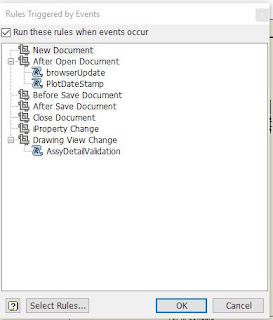
A trigger was set to run the rule after the drawing has been opened.  Additionally, the rule has been defined as an external rule, to allow the rule to more easily be implemented on other systems.

iLogic Code:
 ' Rule Name: dwg11x17print  
 ' Date : 9/7/16  
 ' Purpose:  
 ' iLogic rule to set the printer to 11x17  
 ' and check for the scale via a custom iproperty "plot_scale"  
 Sub Main()  
 Dim oDOc as Document  
 oDoc = ThisDoc.Document  
 If oDoc.DocumentType <> Inventor.DocumentTypeEnum.kDrawingDocumentObject Then  
      Exit Sub  
 End If  
 Dim custPropSet As PropertySet  
 custPropSet = oDoc.PropertySets.Item("Inventor User Defined Properties")  
 Dim oPrintMgr As DrawingPrintManager  
 oPrintMgr = oDoc.PrintManager  
 Dim dScale As Double  
 Dim lPrintScale As Boolean  
 ' Try to see if the custom iProperty exists...  
 Try  
      dScale = custPropSet.item("plot_scale").Value  
      ' MessageBox.Show("Scale custom property = "&CStr(dScale), "iLogic")  
 Catch  
      lPrintScale = InputRadioBox("Select scale for printing","Half scale","Full scale" , True, Title :="SCALE LIST")  
      If lPrintScale Then  
           dScale = 0.5  
      Else   
           dScale = 1.0  
      End If  
 End Try  
 With oPrintMgr  
      .Orientation = kLandscapeOrientation  
      .AllColorsAsBlack = False  
      .ColorMode = 13314 ' Print using a gray scale   
      .ScaleMode = 13827 ' kPrintCustomScale  
      .Scale = dScale  
      .PaperSize = PaperSizeEnum.kPaperSize11x17  
 End With  
 End Sub  

Wednesday, August 17, 2016

Autodesk Inventor - The case of the shifting text...

' http://www.danielhansen.net/2014/06/how-to-format-code-and-syntax.html

First post, of what may be many more, or it could simply be the last, only time will tell.

When using text containing characters with features which hung below the bottom, lower case "g" or lower case "q" or in this instance the forward slash "/". The text would shift up in the sketch.  The sketch was fully constrained and the single line text was bottom justified.

WHAT WE HAD....

WHAT WE WANTED....

THE SOLUTION... 

We posted a query on the Autodesk Inventor forums asking for assistance and within the hour we had a solution.  Set the text justification to baseline, not bottom justification.

Another solution would have been to simply have had the vertical alignment of the text set to center justification.  

The justification configuration was the last piece in the puzzle of the drawing template.  We are going to attempt to keep the number of sheets to a minimum, but we currently can have up to eight sheets in a single file.  

We are using multiple custom iProperties to populate the title blocks of the various sheets along with an iLogic form to assist in filling out the sheets with the proper client information.


Lastly, there is some iLogic code to push the proper sketch symbols for the client and state onto the eight sheets.  

'CODE STARTS HERE:
Option Explicit
Sub Main()

Dim sheetprop As String
Dim iNumSheets as Integer 

Dim oDoc as DrawingDocument 
oDoc = ThisApplication.ActiveDocument

Dim oSheet As sheet
Dim iSheetCount As Integer
Dim i As Integer
Dim j As Integer

' Number of sheets requested in the control panel form
iNumSheets = iProperties.Value("Custom", "SHEET_NUMBER")

' MsgBox("iNumSheets = " & iNumSheets, vbOKOnly,"Number of Sheets")

j = 1
For Each oSheet In odoc.sheets
 sheetprop = "SHEET_"&Trim(Str(j))
 oSheet.Name = iProperties.Value("Custom", sheetprop)
 If j > iNumSheets And j <=8 Then ' Set the sheet flag to false
  'MsgBox("Sheet Number  = " & j, vbOKOnly,"Number of Sheets")
  Parameter(sheetprop & "_CHK") = False
 Else
  If j > 1 Then 
   Parameter(sheetprop & "_CHK") = True
  End If
 End If
 j = j + 1
Next

' Open up the Control Panel
iLogicForm.Show("DRAWING CONTROL PANEL", FormMode.NonModal)
iLogicVb.UpdateWhenDone = True

' Setup the COA number
Dim strState As String = STATE_BORDER 'STATE_BORDER IS A PARAMETER...
Dim strCoaNum as String 

Select Case strState
.
.
.
.
 Case Else
 strCoaNum = "NONE"
End Select

'Push value into the custom iproperty so it can be dropped into symbol
iProperties.Value("Custom", "STATE_COA") = strCoaNum'STATE_COANUMBER
iProperties.Value("Custom", "STATE") = STATE_BORDER
'RuleParametersOutput()

Dim sLogo As String

Select Case CLIENT

 Case Else
  sLogo = "BLANK"
End Select
' MessageBox.Show ( CLIENT & " - " & sLogo,"Client Selected")
' Update the client logo
'MsgBox ("Logo selected: "& sLogo)
If sLogo <> "BLANK" Then Call logoChk(sLogo)

' Set the printer and page size
Dim oPrintMgr As DrawingPrintManager
oPrintMgr = oDoc.PrintManager

With oPrintMgr
 .AllColorsAsBlack = False
 .ColorMode = 13314 ' Print using a gray scale 
 .ScaleMode = 13827 ' kPrintCustomScale
 .PaperSize = PaperSizeEnum.kPaperSize11x17
End With

End Sub

Sub logoChk(sketchAdd As String)
' Code utilizes the last four characters of the symbol name
' to see if the symbol is a logo.  Therefore only use 'LOGO' 
' at the end of the symbol name.

' Insertion point for the current logo and title block (1/22/15)
Dim logopt As Point2D = ThisApplication.TransientGeometry.Createpoint2d(70.1675,7.62)
'logopt.x = 70.1675
'logopt.y = 7.62

Dim oDrawDoc as DrawingDocument
oDrawDoc = ThisApplication.ActiveDocument

Dim oSymDef As SketchedSymbolDefinition    
'MsgBox ("Logo Name = " & sketchAdd)
oSymDef = oDrawDoc.SketchedSymbolDefinitions.Item(sketchAdd)

' MsgBox("Symbol Definition : " & oSymDef.Name)

Dim oSym as SketchedSymbol
' Dim oSheet As oDrawDoc.Sheet

Dim bLogoFound As Boolean = False

Dim insPt2D As Point2D

For Each oSheet In oDrawdoc.sheets
 'MsgBox ("Sheet Number :"& oSheet.Name)
 For Each oSym in oSheet.SketchedSymbols
  If Right(oSym.Name,4) = "LOGO" Then
   ' now we check to see if the logo file matches the 
   ' client selected.
   ' need to have a flag to let the program know 
   ' that a logo was found and replaced or not
   ' MsgBox ("Sheet Number: "&"-"&sketchAdd)
   If oSym.Name  <> sketchAdd Then
    'MsgBox ("Sheet Number:"& oSheet.Name &" - " & oSym.Name &" Check Me.")
    ' Get the insertion point
    insPt2D = oSym.Position
    ' We delete the current definition...
    oSym.Delete
    '...and replace, with a rotation angle of 0 and a scale of 1
    oSym = oSheet.SketchedSymbols.Add(oSymDef,insPt2D,0,1,)
    'MsgBox ("Insertion Point : " & insPt2D.x & "-" & insPt2D.y)
    bLogoFound = True ' Set flag to True
   Else
    blogofound = True
   End If
  End If
 Next
 If bLogoFound = False Then  ' Currently no logo on the sheet
        ' we need to insert a logo into the
        ' proper location
  'MsgBox ("Logo to be added : " & sketchAdd)
  oSym = oSheet.SketchedSymbols.Add(oSymDef,logopt,0,1,)
  bLogoFound = False ' Reset flag
 End If
Next

' Housekeeping:
' Close any expanded nodes on the browswer
Call CloseTree

End Sub 

Sub CloseTree()
'-----start of ilogic-----
'sort components in the browser
'ThisApplication.CommandManager.ControlDefinitions.Item _
'("AssemblyBonusTools_AlphaSortComponentsCmd").Execute

'set a reference to the document
Dim oDoc As Document
oDoc = ThisApplication.ActiveDocument

'Set a reference to the top node of the active browser
Dim oTopNode As BrowserNode
oTopNode = oDoc.BrowserPanes.ActivePane.TopNode

Dim oNode As BrowserNode

For Each oNode In oTopNode.BrowserNodes
 ' If the node is visible and expanded, collapse it.
 If oNode.Visible = True And oNode.Expanded = True Then
  oNode.Expanded = False
 End If
Next

'zoom all
'ThisApplication.ActiveView.Fit
End Sub